


 46 / 74

CARDIOVASCULAR JOURNAL OF AFRICA • Volume 25, No 5, September/October 2014
240
AFRICA
more distal longitudinal flexibility and are designed to prevent
kinking and provide refined adaptation to tortuous iliac arteries.
Finally, the graft delivery system is reduced by approximately
3 French (Fr) sizes from the smallest prior endograft delivery
system. It is available in outer diameters from 18- to 20-Fr for the
main body and from 14- to 16-Fr for the extensions. Bifurcated
main body proximal diameters include sizes of 23, 25, 28, 32
and 36 mm; limb diameters include sizes of 10, 13, 16, 20, 24
and 28 mm. The diameter of the stent-graft is oversized by
approximately 20% in relation to the outer aortic diameter at the
proximal fixation zone and about 10% in the distal landing zones
(usually the common iliac arteries).
Recently, renovation of the Endurant™ system has resulted
in an improved version. Endurant
®
II provides three additional
advanced design features: (1) a 35% extended hydrophilic coating
allows the 28-mm-diameter bifurcated component to fit inside an
18-Fr outer diameter catheter (initially 20-Fr with the original
Endurant); (2) availability of two new contralateral limb lengths
(156 and 199 mm) enables more configuration options and
requires fewer total components; and (3) improved radiopacity
of the distal end of the bifurcated component’s contralateral
gate increases visibility. The Endurant
®
II device received FDA
approval in June 2012.
11
The following technical scenarios are
also applicable to Endurant
®
II.
Technical notes
Scenario 1: Capture of the tip sleeve within the
suprarenal bare-stent anchoring pins
This scenario assumes that the main body of the bifurcated
component of the Endurant
TM
stent-graft is deployed and the
delivery system advanced proximally as far as 3 cm apart from
the suprarenal stent [see manufacture instructions for use (IFU)
for system details]. The next step is very crucial and failure to
withdraw the delivery system until the spindle is retracted into
the fabric portion of the stent-graft results in trapping of a
suprarenal crown within the tapered tip sleeve.
Even though the steps described in the IFU for the Endurant
TM
stent-graft system may be followed accurtely, in some cases,
especially severe angulated necks (
≥
60°), the markedly flexible
delivery system will follow the aortic configuration and stack
within the hooks of the suprarenal stent. To avoid the need for
open conversion, three simple techniques to successfully remove
the delivery system of this endograft are described:
•
The first action is to completely remove the stiff or super-
stiff guide wire (usually Amplatz™, Ontract, Archer™ or
Lunderquist) inside the delivery system, and then rotationally
withdraw the delivery system. Removing the wire allows the
graft to follow the natural aortic anatomy. Under straightfor-
ward circumstances, the device may bend along the body–ipsi-
lateral endograft, possibly avoiding stacking at the level of the
anchoring pins.
•
The above manoeuvre might be performed more safely if
catheterisation of the docking limb and insertion and deploy-
ment of the contralateral limb precedes delivery system with-
drawal. Otherwise its removal may be facilitated by keeping
the contralateral limb in place while moderately inflating (less
than the suprarenal aortic diameter) the molding balloon (e.g.
Reliant
®
, Equalizer or Coda) at the pins’ level prior to down-
ward removal of the delivery system (Fig. 1A, 1B).
•
When compelling anatomical conditions exist, another option
is to place a large introducer sheath (e.g. Cook 16- or 24-Fr),
through the already catheterised docking limb, advancing
above the suprarenal stent before delivery system withdrawal.
This manoeuvre leads to aorto-iliac axis ‘technical remodel-
ling’ with further proximal neck straightening, a condition
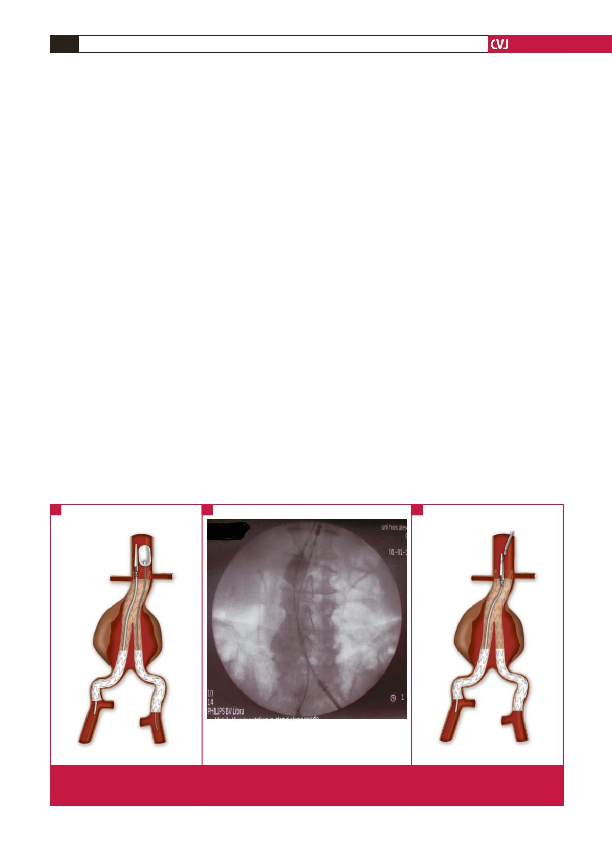
Fig. 1. (A) Inflation of the moulding balloon at the level of the pins prior to downward removal of the delivery system. (B) Angiogram
showing the above manoeuvre. Note the balloon that pushes the delivery system in the opposite direction. (C) Use of a snare
device to capture the spindle, while simultaneously retracting the delivery system with slow rotational movements.
A
B
C