
CARDIOVASCULAR JOURNAL OF AFRICA • Volume 25, No 5, September/October 2014
AFRICA
241
that may help to alter the path that the system follows when
rotated downwards for removal. The proximal neck might
also be straightened after placing a super-stiff or extra-stiff
guide wire from the left brachial artery and through the endo-
graft to exit from the contralateral femoral side.
•
The last option replaces the guide wire with a snare device
that is introduced through a 7-, 12- or 14-Fr sheath via the left
brachial artery access, and captures the spindle while simul-
taneously retracting the delivery system with slow rotational
movements (Fig. 1C).
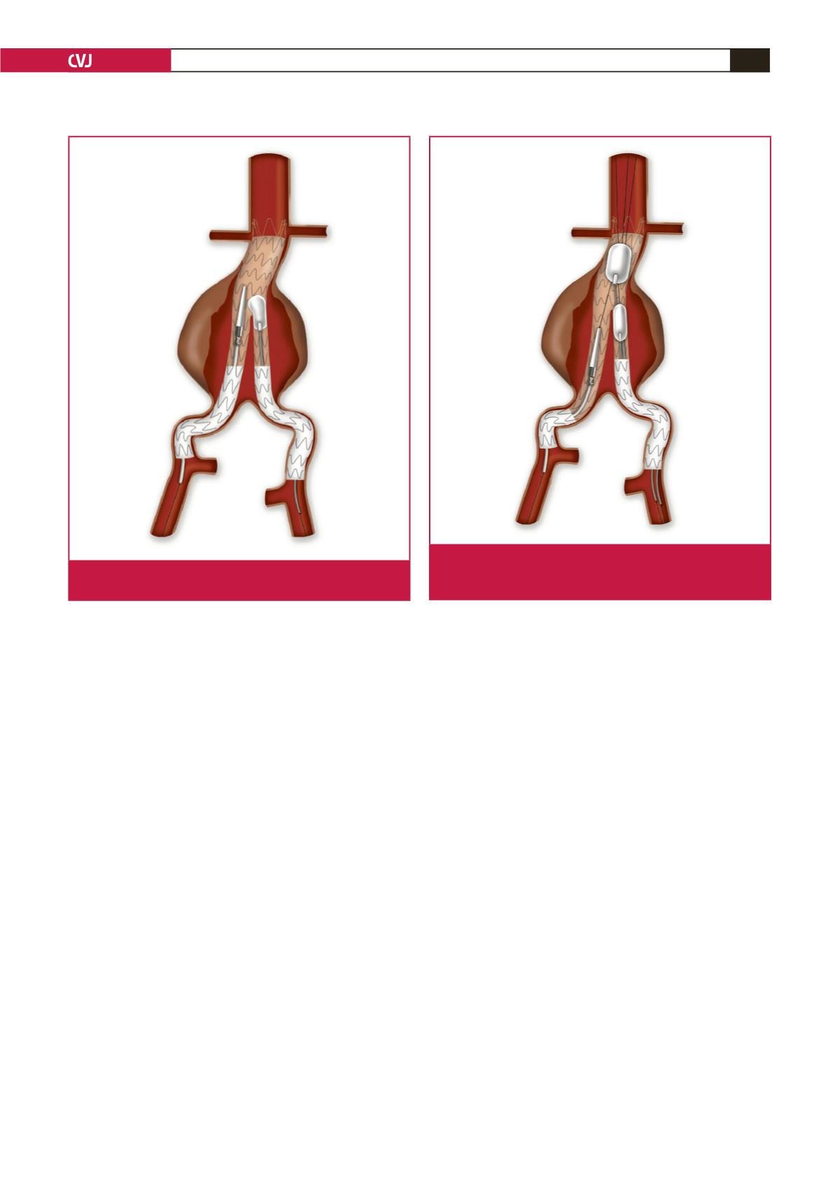
Scenario 2: The delivery system blocks at the flow
divider level
In this situation the delivery system moved slightly upwards.
The troubleshooting technique includes first deployment of the
contralateral limb in the standard fashion, followed by insertion
of a moulding balloon (e.g. Reliant
®
, Equalizer or Coda), which
is inflated in the same manner as required to push the delivery
system to the ipsilateral endograft wall, when the latter is
retracted slowly (Fig. 2).
Scenario 3: The delivery system blocks at the
ipsilateral limb
Two moulding balloons (e.g. Reliant
®
, Equalizer or Coda) are
required in this situation. They are inserted through a 14-Fr
Cook introducer sheath from the contralateral site after the
contralateral limb is completely liberated and dilated. One
moulding balloon is positioned above the flow divider and
the second one at the body-to-contalateral limb overlapping
area. They are simultaneously dilated and kept in a constant
position, thus stabilising the endograft while the delivery system
is withdrawn from the ipsilateral limb (Fig. 3).
The same concept may be applied with a larger balloon
coming from above through the left brachial artery. In this case
the balloons are inflated and retracted in opposite directions.
This bidirectional balloon retraction allows more powerful
downward movement of the delivery system.
Scenario 4: The delivery system blocks at the
external iliac artery
The only way to avoid open conversion in this scenario is to
perform a balloon angioplasty of the external iliac artery.
Catheterise the delivery system, insert a second 180-cm (0.035-
inch) hydrophilic wire between the delivery system and the
arterial wall, and place it into the aneurysm sac (Fig. 4A, 4B).
A small-diameter (4–6 mm) balloon is introduced over the wire
and then into the external iliac artery. Under low pressure,
angioplasty is performed. It is not required to fully dilate the
balloon up to 8 Atm since the purpose is just to freely remove the
delivery system from the stenotic area. In this scenario not only a
guide wire, but even a sheath and later a balloon, can be inserted
through the delivery system.
Discussion
Improvements in the endovascular stent-graft design, device
delivery and deployment characteristics have all resulted in
Fig. 2. The balloon pushes the delivery system to the ipsilat-
eral endograft wall when the latter is retracted slowly.
Fig. 3. The balloons are simultaneously dilated and kept in a
constant position, thus stabilising the endograft while the
delivery system is withdrawn from the ipsilateral limb.


