


 55 / 68

CARDIOVASCULAR JOURNAL OF AFRICA • Volume 26, No 3, May/June 2015
AFRICA
e5
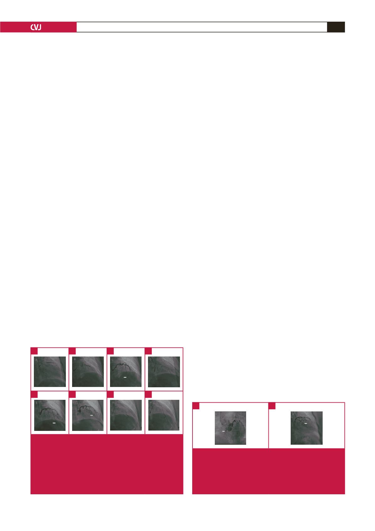
the juncture of the diagonal branch and the LAD artery, and to
position a guide wire in the artery to protect it (Fig. 2A).
After stent implantation, the guide wire was set for expansion
(Fig. 2B). After expansion, angiography showed no mezzanine,
side branch occlusion or residual stenosis at the implantation
site, and forward blood flow was TIMI grade 3. However,
contrast agent overflow was seen at the distal left LAD artery
(Fig. 2C). The patient did not experience discomfort and had
normal blood pressure with a steady heart rate. As the guide
wire did not reach the distal vessel through the perforation site
even after several attempts, it was positioned proximal to the
perforation site, and a balloon was used for compression (Fig.
2D). Because this did not successfully close the perforation (Fig.
2E), a coil was used to achieve successful closure (Fig. 2F), after
obtaining the consent of family members.
Discussion
The incidence of coronary perforation during PCI is low, but it
has a relatively high mortality rate. The available data show that
the female gender, increasing age, treatment of a chronic total
occlusion, angiographic evidence of calcification, and use of a
cutting balloon or rotational atherectomy are associated with
increased risk of coronary perforation.
3–14
In a randomly assigned case–control study conducted
between 2001 and 2008, Shimony and colleagues found that
the strongest predictor of coronary perforation was treatment
of a chronic total occlusion.
9
Gruberg
et al
. identified age and
cardiac tamponade as predictors of mortality among patients
with coronary perforation.
11
A classification scheme has been developed to help in the
management of patients with perforation and to assist in delivery
of optimal care.
10
Coronary perforation is divided into three
classes based on angiographic appearance: I, extraluminal crater
without extravasation; II, pericardial or myocardial blushing;
III, perforation ≥ 1 mm in diameter with contrast streaming
and cavity spilling, i.e. perforation into an anatomical cavity,
chamber, or coronary sinus (Ellis type III CS).
Managing coronary perforation during PCI requires an
accurate diagnosis of the type of perforation that has occurred.
Adverse clinical outcomes (e.g. death or emergency surgical
exploration) are associated with angiographic classification of
the perforation, and have been more frequently observed in
patients who experienced a class III coronary perforation.
8–10,14
The management of coronary perforation often includes heparin
reversal, discontinuation of glycoprotein IIb/IIIa inhibitors,
platelet transfusion, pericardiocentesis, and emergency cardiac
surgery. Additional treatment strategies include prolonged
balloon inflation, covered stents, injection of polyvinyl alcohol,
coil embolisation, and intracoronary administration of
autologous blood.
17–21
This patient had normal blood pressure, a steady heart rate
and no manifestations of cardiac tamponade during the three-
hour procedure. Although balloon occlusion was used within
an hour to apply pressure, rapid outward bleeding continued for
more than two hours. Ultrasound monitoring of the pericardial
cavity was performed during the entire procedure, and overflow
into the pericardial fluid was not observed. Imaging showed that
the contrast agent overflow visible at the base of the heart in the
systolic phase (Fig. 2G) dissipated quickly during diastole (Fig.
2H). Overall, the evidence indicated that this was an Ellis type
III CS coronary perforation that penetrated a ventricular cavity.
Evidence for perforation of the right ventricle included the
following reasons. First, overflow of contrast agent occurred
in both systole and diastole, which is consistent with the
haemodynamic properties of the coronary artery and right
ventricle. If the left ventricle had been perforated, the contrast
agent would have been much more evident in diastole than
in systole. Second, images from the left anterior oblique
position showing the anatomy of the right ventricle support
this interpretation (Fig. 3A). Third, the velocity of the contrast
agent overflow was similar to the right ventricular flow velocity,
but much slower than the intra-aortic flow velocity (Fig. 3A).
This patient was a 69-year-old woman. The hydrophilic
coated guide wire used for expansion and the V-shaped
anatomical structure proximal to the perforation site may also
have contributed to the perforation (Fig. 3B). Others have
found that LAD arteries and tortuous lesions were vulnerable to
perforation, and that the guide wire was frequently responsible
for the perforation.
8,14
Therefore special care should be exercised
to avoid perforation when performing PCI in older females with
special anatomical structures.
In the treatment of this patient, balloon compression was
unsuccessful. Stent implantation was not considered because the
Fig. 2.
(A) A guide wire positioned at the junction of the diago-
nal branch and the LAD artery. (B) Resetting the guide wire
for expansion. (C) Contrast agent overflow is shown at the
distal LAD artery. (D) Balloon for compression. (E) Perforations
that have not been successfully closed by the balloon. (F)
Successful closure achieved using a coil. (G) Contrast agent
overflow to the base of the heart in the systolic phase. (H)
Dissipation of the contrast agent in the diastolic phase.
A
E
B
F
D
H
C
G
Fig. 3.
(A) Images from the left anterior oblique position show-
ing the anatomy of the right ventricle. The velocity of the
contrast agent overflow was similar to the velocity of the right
ventricular flow but much slower than the intra-aortic velocity.
(B) The atypical V-shaped anatomical structure proximal to the
perforation site.
A
B